PSP/FIELDS data release 8 (2021 June 28) includes survey data from PSP Encounter 7 and Venus Gravity assist 4. Several data sets have been updated in release 8.
Data set update: MAG data
All FIELDS fluxgate magnetometer data have been reprocessed, and the version number of the CDF files has been incremented from v01 to v02. Version 2 of the MAG data includes several changes.
MAG offsets
The zero levels (also known as offsets) for the MAG sensors are time-dependent, and are determined using analysis of magnetic field measurements during spacecraft maneuvers, as well as Alfvénic rotations in solar wind data (Bowen et al. 2020). In Version 2 of the MAG data, these offsets are now interpolated during the Encounter phase of each orbit (when PSP is within 0.25 AU).
This affects data during the Encounter phase, and can result in an offset change of up to ~2 nT at closest approach in the final Level 2 data. The updated time-dependent MAG offsets are included as metadata in the Level 2 MAG CDF files.
Spacecraft to RTN coordinate rotation
MAG data products are rotated from spacecraft coordinates into RTN (and, for times near Venus flyby, VSO) coordinates. In Version 1 of the MAG data, the time input to this rotation matrix calculation was incorrect, resulting in a rotation matrix that was several seconds off of the correct matrix. In Version 2, this has been corrected.
This correction only affects RTN and VSO data recorded while the spacecraft is changing its attitude–for example, during a FIELDS MAG rotation, or when the spacecraft changes orientation to point a communication antenna towards Earth. During the Encounter phase, spacecraft attitude is nearly constant, so this change does not significantly affect Encounter data.
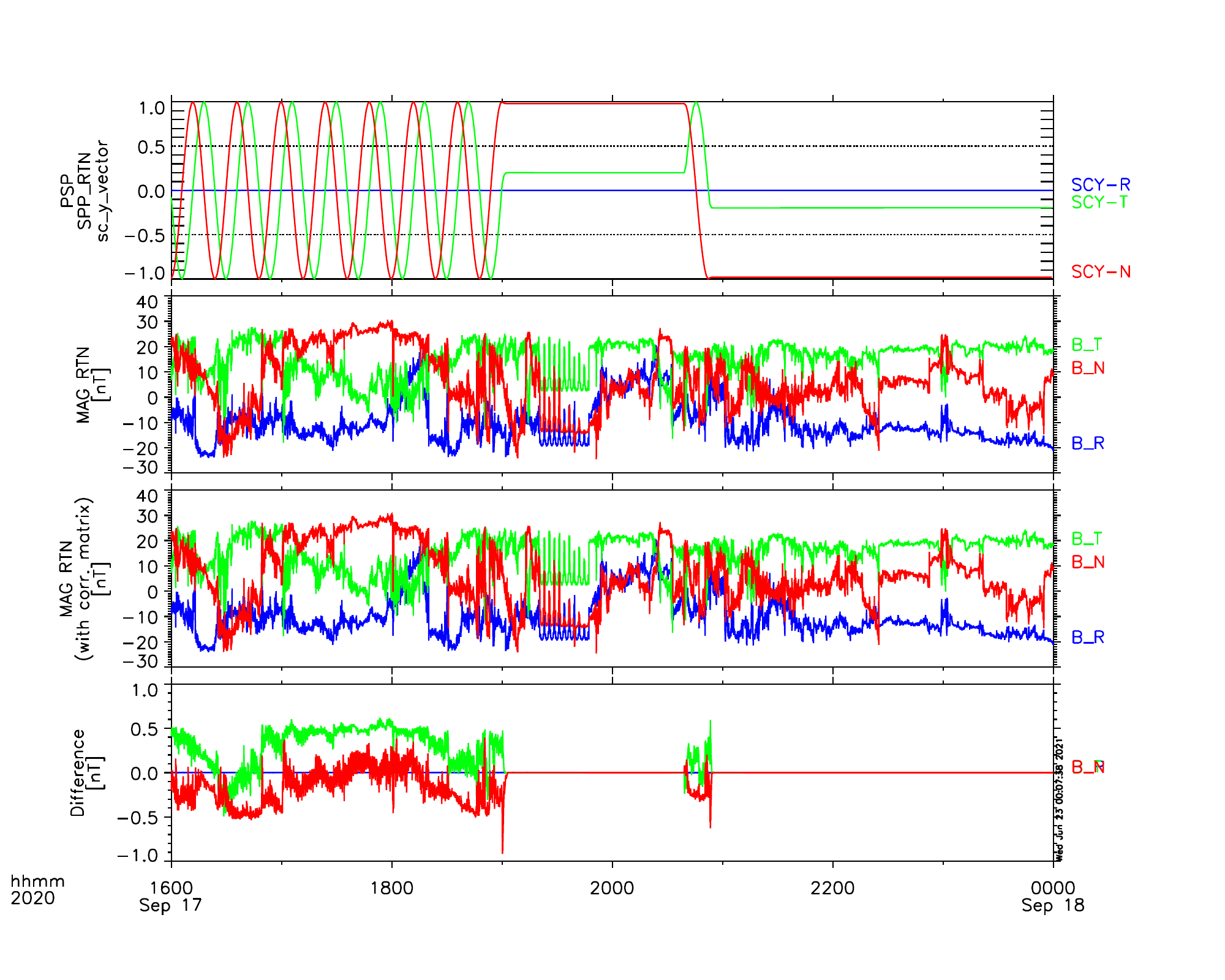
During maneuvers such as the FIELDS MAG rotations, the spacecraft angular velocity is approximately 0.25 degrees/second, so an error of several seconds is around one degree. At typical field amplitudes outside of Encounter, a one degree error in attitude corresponds to an error in field components of ≲1 nT. The figure below illustrates the effects of the change during an interval on 2020 September 17. This interval includes the end of a FIELDS rotation at about 19:00, and a spacecraft attitude change just before 21:00. The attitude changes corresponding to these activities are indicated in the top panel, which shows the spacecraft Y axis projected into RTN coordinates. The second panel shows Version 1 of the MAG RTN data, and the third panel shows the same data, with the Version 2 rotation correction applied. (For purposes of this plot, only the RTN matrix correction has been applied, not the other corrections described in these notes.) The bottom panel shows the difference between the second and third panels. The difference is notable while the attitude of the spacecraft is changing, and negligible when the attitude is constant. The R component of the field is unaffected, because these maneuvers took place when the spacecraft Z axis was aligned with the radial direction (as is the case during Encounter), and the maneuvers consisted of rotations about the spacecraft Z axis.
Triangle filter compensation
Full cadence MAG data is produced on the spacecraft at a cadence of 293 Sa/second, or 256 Sa/Cycle. To conserve telemetry when PSP is far from perihelion, this MAG data is often downsampled onboard by factors of 2^N, using an onboard triangle filter. In addition to onboard downsampling, the FIELDS SOC produces downsampled data products at cadences of 4 Sa/Cycle and 1 Sa/minute.
The triangle filter introduces a shift in the downsampled time series of 1/2 of the sampling cadence–i.e, data downsampled from 256 Sa/Cyc to 128 Sa/Cyc exhibits a shift of 1/256 of a cycle. In Version 1 of the MAG data, correction for this effect was not implemented in the full cadence MAG data products (mag_SC, mag_RTN). Correction was implemented in Version 1 of the 4 Sa/Cyc downsampled product, using a change in the time stamp of each sample.
In Version 2 of the MAG data, the triangle filter is compensated using a convolution kernel which corrects the time shift while retaining the original timestamps in the time series.
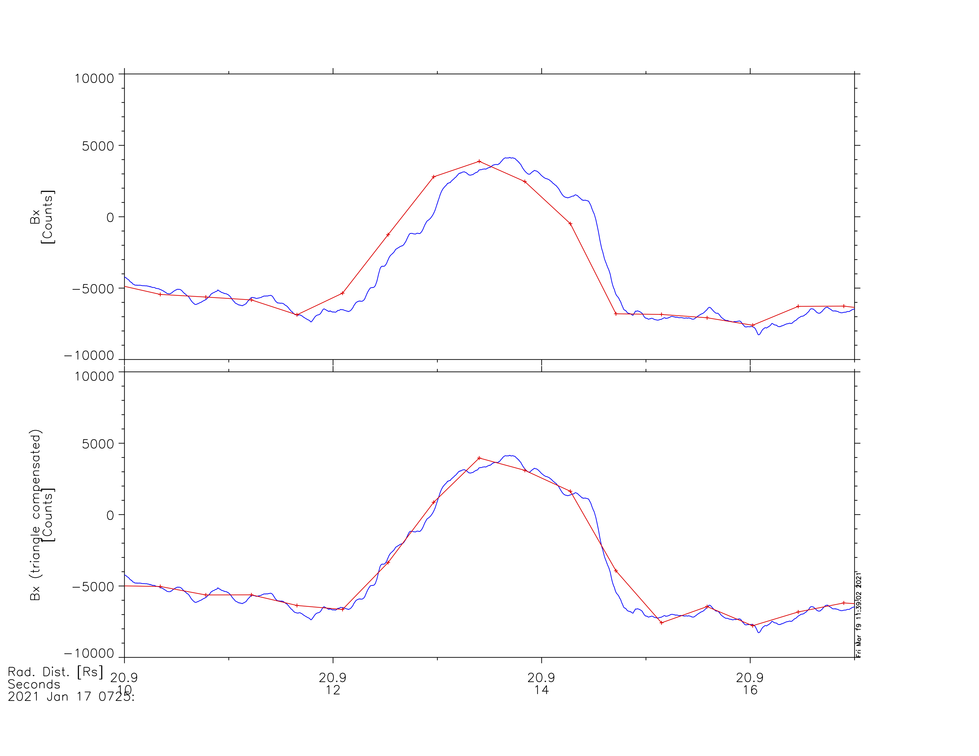
An example of the effect of this correction is illustrated below, using Level 1 data from the inboard and outboard MAG data during Encounter 7. These Level 1 data are shown in telemetry count units. During this interval, the outboard MAG (shown in blue) was recording data at 256 Sa/Cyc, while the inboard MAG (shown in red) was recording data at 2 Sa/Cyc. The top panel shows inboard MAG data without correction for the downsampling time shift (as in Version 1 of MAG data), while the bottom panel shows the inboard MAG data compensated for the effect of the triangle filter (as in Version 2).
This correction affects the mag_SC, mag_RTN, mag_SC_4_Sa_per_Cyc, and mag_RTN_4_Sa_per_Cyc data products. This correction does not affect the 1 minute MAG data products–the 1 minute data are not downsampled with a triangle filter, they are simply averaged over 1 minute intervals.
SCaM two-axis data
As noted previously, one axis of the search coil magnetometer (the low frequency SCM u axis) has not functioned properly since March 2019 (prior to Encounter 2). Therefore, producing a full three-axis merged Search Coil and fluxgate Magnetometer (SCaM) data set is only possible for Encounter 1 (and Venus Gravity Assist 1).
A new version of the SCaM data set (Version 2) has been produced, which now includes a two-axis merged data set. The fluxgate MAG data has been rotated into the frame of the two functional SCM coils (the v and w) axes, and merged with the SCM waveform data from those coils.
The new version of the SCaM data set also includes merged data in the RTN coordinate system–however, these only contain valid data for Encounter 1 and Venus Gravity Assist 1.
High frequency noise during Encounter 7
During Encounter 7, intermittent high frequency noise was present in FIELDS measurements made by the RFS and TDS receivers. The RFS, which is the most sensitive FIELDS receiver, was more strongly affected.
The two-channel RFS receiver made measurements using the V1-V2 dipole on one channel and the V3-V4 dipole on the other channel. Several times during the encounter, noise was observed on one dipole but not the other (usually on V1-V2 and not on V3-V4). For most of these noisy intervals, the noise was present in the LFR frequency range, below the plasma frequency.
However, during two intervals on January 16th and January 19th, narrowband noise lines were extended into the HFR frequency range. TDS waveforms recorded during these intervals allowed for detailed frequency analysis of the noise, revealing narrowband signals at around 170 kHz and harmonics. The TDS analysis also indicated that the noise was primarily in V2 during Encounter 7. An example RFS interval from January 16th is shown below. The top panels show the V1-V2 data, the bottom panels show the ratio between V1-V2 and V3-V4, showing that the noise is prevalent in the V1-V2 channel.
The exact physical mechanism of the noise has not been determined conclusively, but the noise may be related to excess bias current on the V1-V4 antennas. During Encounter 8, excess bias current drove the V1 and V2 antennas to large negative potentials, affecting not only the high frequency TDS and RFS measurements, but also the lower-frequency DFB measurements. For the upcoming Encounter 9, FIELDS plans to reduce the bias current applied at a given distance from the Sun.

A list of times where the noise appeared during Encounter 7 is provided below. The note indicates which RFS channel exhibits the noise, and whether it is present in LFR and HFR, or LFR only. The data intervals with noise present are included in the files. When analyzing FIELDS data from these intervals, users of RFS and TDS data are advised to use V1-V2 data with caution, and to consult with the FIELDS team if there is any doubt whether any observed phenomena are real or instrumental in origin.
Updated on 2021 October 28: See release notes for release 9 for additional details.
START               STOP                    NOTE
2021-01-16/09:33:30 2021-01-16/11:49:30 V12 LFR + HFR
2021-01-16/13:16:08 2021-01-16/13:25:00 V12 LFR
2021-01-16/13:55:42 2021-01-16/14:16:05 V12 LFR
2021-01-16/15:21:50 2021-01-16/17:01:20 V12 LFR
2021-01-18/04:39:10 2021-01-18/05:34:30 V12 LFR
2021-01-18/12:06:00 2021-01-18/12:49:20 V34 LFR
2021-01-18/15:16:15 2021-01-18/15:20:45 V12 LFR
2021-01-18/15:42:20 2021-01-18/16:26:25 V12 LFR
2021-01-18/17:52:00 2021-01-18/18:45:00 V12 LFR
2021-01-19/16:23:40 2021-01-19/17:46:05 V12 LFR + HFR
2021-01-21/07:46:52 2021-01-21/08:20:40 V12 LFR