PSP/FIELDS data release 5.1, on October 19, 2020, updates the dfb_dbm_scm and dfb_wf_dvdc data types to version 3. The new data versions contain significant corrections to the previously released data, as detailed below.
DFB DBM SCM waveform
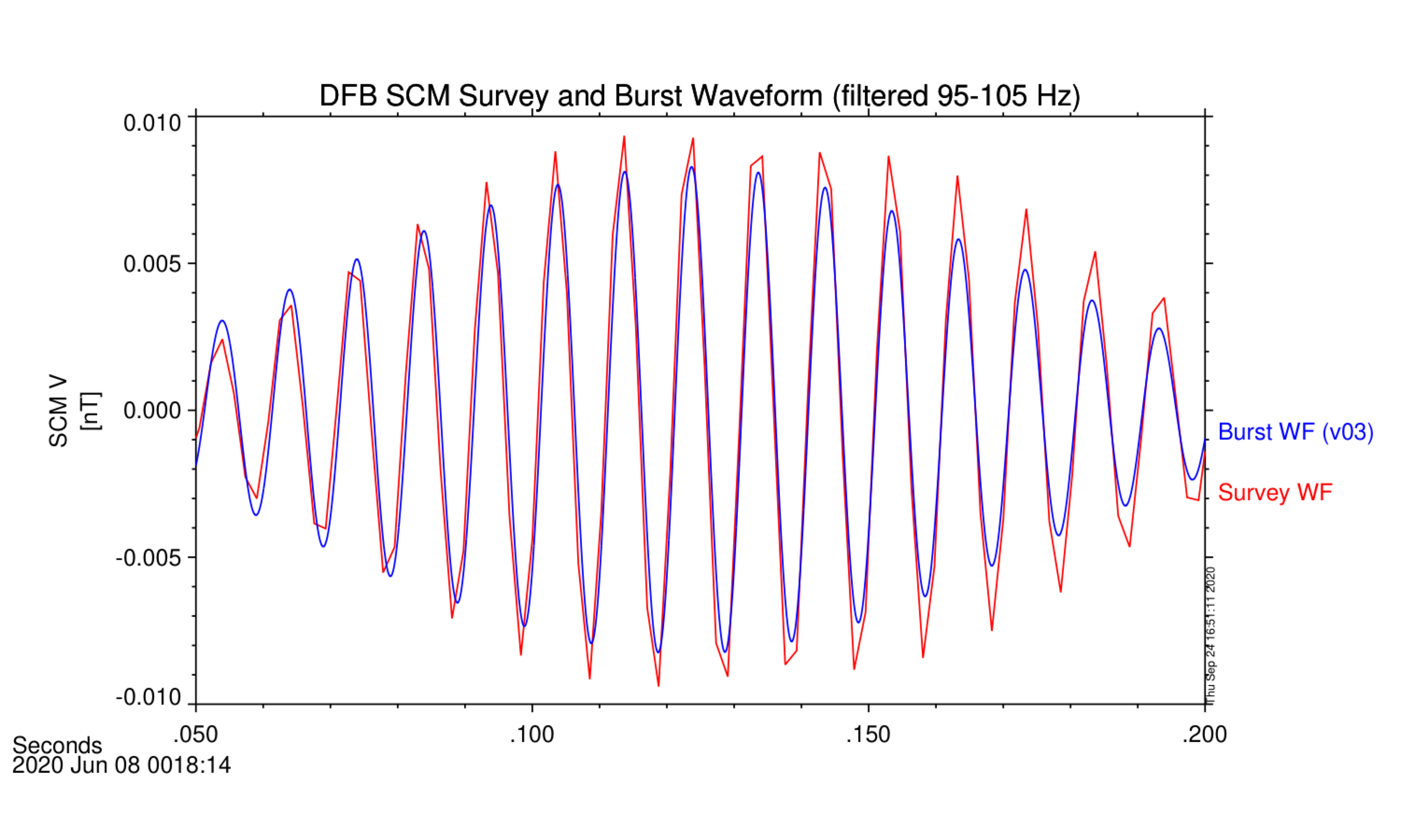
Version 3 of the Level 2 DFB DBM (burst waveform) corrects a sign error in the SCM burst kernel. After this correction, the DBM SCM file is consistent with lower cadence data products such as the SCM survey waveform (dfb_wf_scm) and the merged fluxgate and SCM (merged_scam_wf).
The DBM SCM files now also combine high and low gain waveforms in a single file. Variable names now include hg or lg to indicate the gain state–for example, the burst capture from the u axis of the SCM was included in v02 as psp_fld_l2_dfb_dbm_scmu, and in v03 is included as two separate variables, psp_fld_l2_dfb_dbm_scmhgu and psp_fld_l2_dfb_dbm_scmlgu.
Note that these variables may have zero records in the CDF file, if zero high gain or zero low gain burst waveforms were recorded during a given interval.
During Encounters 3 and 4, most SCM burst waveforms were recorded in low gain mode, due to large intermittent signals related to the SCM anomaly described here. Starting from Encounter 5, the DFB was configured to always record SCM burst waveforms in high gain.
DFB differential voltage waveform
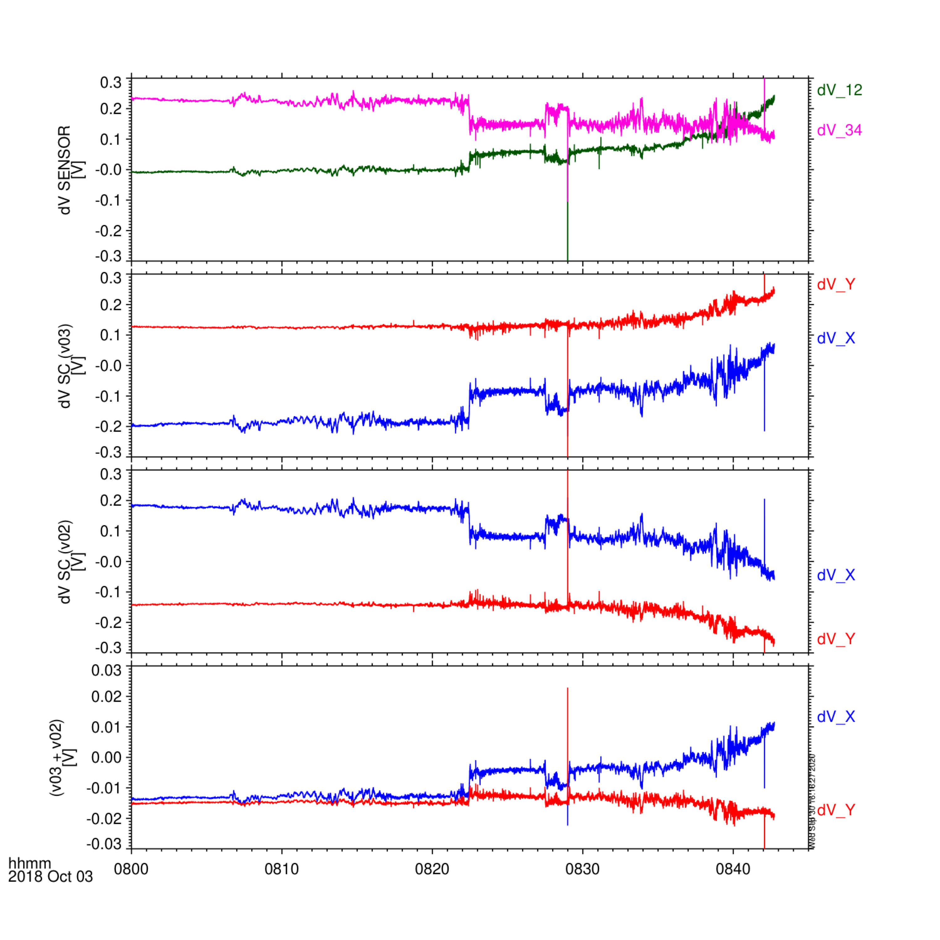
Version 3 (v03) of the Level 2 DFB differential voltage survey waveform files corrects the transformation from sensor coordinates to spacecraft coordinates. This correction includes two changes.
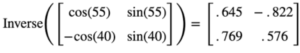
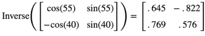
- The V12 and V34 dipoles are not orthogonal–in the plane of the PSP heat shield, the angle between the V12 dipole and the V34 dipole is 95 degrees (V12 is 55 degrees from the spacecraft X axis, and V34 is -40 degrees). Therefore, the appropriate matrix from sensor to spacecraft coordinates is the matrix below. This matrix is included as non-record-varying metadata in the v03 CDF files. This correction introduces a ~10% difference in the spacecraft coordinate differential voltage data, compared to v02 files.
- There is an overall sign change in the spacecraft coordinate waveforms. The data contained in these Level 2 files is differential voltage data (in Volts), not electric field data (in Volts/m). The sign for these data types is generally opposite: i.e. a positive dVx corresponds to a negative Ex. In previous versions (up to v02) the sign chosen was appropriate for electric field data, not differential voltage data. This is corrected in v03.
Note: The FIELDS team continues to actively work on the electric field data product, which requires calibration of the frequency-dependent antenna effective vector. The electric field data will be included in an upcoming data release, as a Level 3 data product.
SCM and voltage sensor inter-calibration
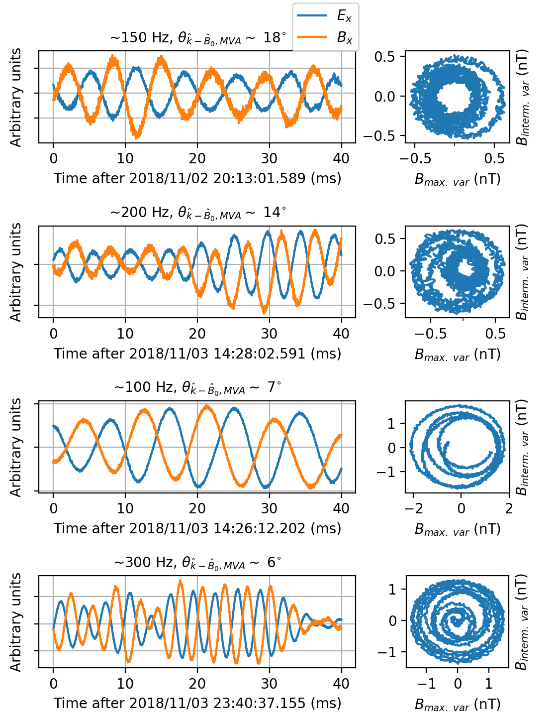
The FIELDS team continues to work on calibration of SCM and voltage sensor burst waveform data. In particular, we are investigating the phase relation in these data products for electromagnetic whistler waves at ~100 Hz.
The figure below shows several examples of waveforms with SCM and voltage data for whistler waves, where the whistler wave propagation angle is close to the background field. From theory, we expect a phase difference of ~90 degrees between magnetic and electric field components, but this is not the case. It is likely that this difference is due to instrumental effects and not physics.
Scientists working with these data products are highly encouraged to contact the FIELDS team and join this ongoing discussion.